poly2dRpt: Using the Dialog
Table of Contents
- Overview
- Input directory or Input Object
- Report Comma Delimited File (*.CVS)
- Spawn Comma Delimited File (*.CVS) Report
- Report Styles
- Options
- Selecting Report Fields
- Selecting which Items to Report
- Ordering the Report Fields
- Available Items to Report
- Save Responses
Overview
Presents GUI when run without any arguments. The following values are available in the panel.
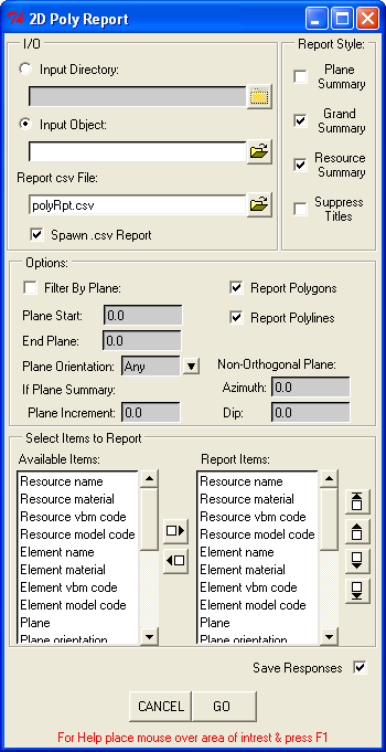
The Polyline 2D Report Dialog
Input directory or Input Object
Specify either an input directory containing geometry objects or an input geometry object then enter or browse for the directory path or msr file.
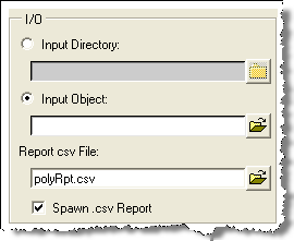
Entering Input/Output (I/O).
If a directory is specified, all geometry objects in that directory will be inspected for polyline/polygons. If a single object is specified, all polylines/polygons within that object are selected.
Report Comma Delimited File (*.CVS)
Enter or browse for the output report file, which is normally a .csv file. (comma delimited). The path can be an absolute path or just the file name, in which case it is written to the current directory.
Spawn Comma Delimited File (*.CVS) Report
Check if you want the report to be automatically spawned by its default associated application, usually Excel for .csv files and Notepad for .txt files.
Report Styles
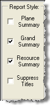
Defining Report Styles in Poly2dRpt
Plane Summary
If Plane Summary is checked the report is subdivided and values are totaled by the distance specified in "Plane Increment" in the OPTIONS section of the panel. Addtionally, "Plane Start", "End Plane" and "Plane Orientation" must be entered to summarize by plane.
To summarize by all the natural planes in the input data, enter a Plane Increment of zero.
To summarize all the data in the input data at the specified Plane Orientation, enter an inclusive range such as "Plane Start" of -9999999, and "End Plane" of 9999999.
For non-orthogonal planes, an azimuth and dip is required and only planes parallel (having the same azimuth and dip) are selected.
Note
Plane Summary may be time consuming depending on the input data.
Grand Summary
If Grand Summary is checked all the rows of data in the report are totaled and the totals are reported on the last line of the report matrix.
Resource Summary
If Resource Summary is checked a addtional matrix is writen to the report file below the main report. The Resource Summary consists of totals by selected catagory for each input geometry object.
Suppress Titles
If suppress Titles is checked, colume titles will not be printed to the report in some cases. If the report file will be input to a subsequent process, this option may be used.
Notes on Summaries
Depending on the field or item being reported, the summary of that item may be a frequency, a total, or a count of the number of different occurances.
For example, 'Area' will be summarized by adding all the areas of each polygon - a total; 'Resource name' summary field reports how many different msr files were included in the report - the number of unique occurances; 'Self intersecting' summary is a count of features that are self-intersecting.
Options
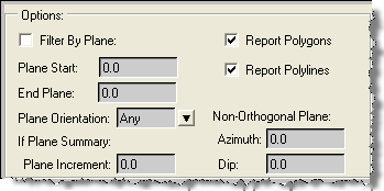
Available options
Filter By Plane
If "Filter By Plane" is checked, only polys with planes matching the filtering criteria are reported.
Filtering criteria are "Plane Start", "End Plane" and "Plane Orientation". If "Plane Orientation" is set to 'NonOrtho', Azimuth and Dip must be entered to define the non-orthogonal plane.
Plane is computed from the plane equation Ax+By+Cz+D=0.
If reporting Non-Orthogonal planes, values for "Plane Start", "End Plane", and "Plane Increment" are distances from the origin. The $dist function of MineSight(R) Grid Set labeling can be used to determine appropriate plane values.
Plane Start
Plane Start is the beginning plane number of the range of planes that will be included in the report. Plane Start is a required field if either 'Filter By Plane' or 'Plane Summary' is checked.
To include all planes in the report when the range of planes is unknown, set "Plane Start" to -99999999 and "End Plane" to 99999999.
End Plane
End Plane is the last plane of the range of planes that will be included in the report. End Plane if a required field if either 'Filter By Plane' or 'Plane Summary' is checked.
Plane Orientation
Plane Orientation is the plane the polylines are snapped to. Plane Orientation is a required field if either 'Filter By Plane' or 'Plane Summary' is checked.
The following values for plane can be selected:
- ::
** If summarizing by plane is checked, "Any" is not a valid selection for "Plane Orientation".
* If either filtering or summarizing by a non-orthogonal plane, azimuth and dip must also be entered to specify that plane. And only elements lying on planes parallel to that azimuth and dip are selected.
Plane Increment
Plane Increment is the distance to group features in counting from plane start to end plane if 'Plane Summary' is checked.
Report Polygons
If "Report Polygons" is checked all 2D polygons in the geology objects are reported.
Report Polylines
If "Report Polylines" is checked all 2D polylines in the geology objects are reported.
Azimuth
If "Plane Orientation" is 'NonOrtho', the azimuth and dip defining that non-orthogonal plane must be specified.
Dip
If "Plane Orientation" is 'NonOrtho', the azimuth and dip defining that non-orthogonal plane must be specified.
Selecting Report Fields
This section allows the selection of items to be included in the report and the positional placement of that item in each of the rows of the comma delimited report.
Lets you select items that you wish to report on.
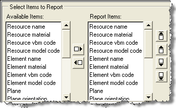
Selecting which Items to Report
From the list of 'Available Items:', highlight those fields wanted in the report and click the 'move right' arrow to move them into the 'Report Items:' column.
Alternatively, to remove fields not wanted in the report, highlight those fields in the 'Report Items:' column and click the 'move left' arrow to remove them from the list.
Ordering the Report Fields
The position of the fields in the 'Report Items:' column represents the order of the fields in each row of the report. For example, if "plane" is the first item in the 'Report Items:' box, it will be the first column of each row in the report.
To move items to the positions desired, use the arrows to the right of the 'Report Items:' box to reposition the items to 'top', 'up one', 'down one' and to the 'bottom' of the list.
Available Items to Report
Plane
Plane is the distance from origin of the polyline's plane.
For example, for plan objects, the plane is the bench or elevation.
For non-orthogonal elements, plane is the same value assigned when creating a non-orthogonal grid set with default labeling in MineSight(r), which is the $dist.
Plane orientation
Plane orientation is one of the following:
- EW Section (North)
- NS Section (East)
- Plan (Elev)
- NonOrtho
Resource Name
Resource name is the name of the geometry object (.msr file name).
Resource Material
Resource material is the material assigned to the resource object (.msr).
Resource VBM Code
Resource vbm code is the vbm code assigned to the resource object's material.
Resource Model Code
Resource model code is the model code assigned to the resource object material.
Element Name
Element name is the attributed name of the polygon or polyline element.
Element Material
Element materail is the attributed material of the polygon or polyline. If the element has no name, it inherits the material of its resource object.
Element VBM Code
Element VBM code is the vbm code of the polygon or polyline material.
Element Model Code
Element model code is the model code of the polygon or polyline material.
Total pts
Tot pts is the number of nodes (points) in the polyline or polygon. For polygons the first and last point will be the same.
Start end pts
Start end pts is the first and last point of the polyline or polygon. For polygons the first and last point will be the same.
Area
The area of the polygon on its plane. Polylines will not have an area because they are not closed.
Length
The length of segments along the point list. Traverses the points list and returns the total length. Just like walking along the line with a pedometer in 3D space.
Length in plan
The length of segments in plan.
Feature type
'Polyline' or 'Polygon'.
Feature Invalid
- Boolean:
- 0 = FALSE
- 1 = TRUE
Set to one (1) if feature is not valid or zero (0) if the feature is okay.
For each polyline, the point list is validated to ensure it is triplet floats.
For each polygon, checks that the pointlinst is valid as above, in addition to checking that there are four or more points, that the pointlist is closed (1st pt = last pt) and that there are no duplicate consecutive points.
Direction ccw
- Boolean:
- 0 = FALSE
- 1 = TRUE
Direction counter clockwise will be equal to one (1) if the polyline was drawn in a counter clockwise direction.
It will be equal to zero (0) if it was digitized in a clockwise direction.
Open
- Boolean:
- 0 = FALSE
- 1 = TRUE
If the element is open it will be equal to one (1). If it is closed, it will be equal to zero (0).
All true polygons are closed and polylines can be open or closed, where closed is defined as the first and last points being equal.
Self intersecting
- Boolean:
- 0 = FALSE
- 1 = TRUE
If the polygon or polyline has line segments that intersect, "Self intersecting" will be set to one (1). If none of the line segments in the feature intersect "Self intersecting" is set to zero (0).
Notes
Speed
Choosing to report whether features are self-intersecting greatly increases the execution time of this script. Only select this item if it is absolutely necessary. The reason that the self-intersecting check takes so long is because each line segment in each poly is compared to all the other segments in that poly:
A loop that is iterated (n(n-1) / 2 - (n-1)) times for every poly encountered, where n = the number of nodes in that poly.
This means iterating about 8,000,000 for a single polygon with 4,000 points vs. less than 6000 for 1000 polygons with 4 points each.
Inconsistence with MineSight(R) 3D Results
Occasionally poly2drpt.py reports a self- intersection that is not reported by the MineSight(r) 3D (MS3D) polyline -> self-intersecting polylines function.
An example of this is a polyline that doubles back on itself. MS3D may not flag this as self-intersecting, but this script will. The reason it is not caught in MS3D is because these cases do not affect model coding.
Note: Checking self-intersection in MineSight(r) 3D
To check a polygon for self-intersections in MineSight(R), select the polygon and do a triangulate surface inside polyline boundary. This flags the self intersections. Or, use point snap, make an edit grid by snapping to 3 points on the polyline, and use the self-intersecting function under the polygon menu.
Save Responses
If "Save Responses" is checked, a configuration (.ini) file is created in the current directory containing the information entered in the panel. These values are used to populate the panel the next time the script is run.
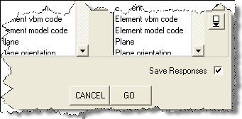
Click Save Responses to generate an INI file containing the information entered in this dialog.
The .ini file is always named poly2dRpt.ini or the name of this script with a .ini extension.
As long as "Save Responses" is checked, the .ini file will be rewritten after each run.
If no .ini file exists, the panel is populated from internal values stored in the script itself to be used as default values.
If the script is run in silent mode, the values in the .ini file are used for the run.
If there is no .ini file, the default values internal to the script are used.
(See General Help by pressing F1 in any area outside boxes in the panel for mode info.)