Delaunay Triangulation (DTB) is the engine behind triangulation of survey data. The name DTB is derived from Delaunay Triangulation with Break lines. Survey data can consist of points and strings which are used to create a mesh of triangles.
Examples using DTB are discussed below.
The syntax for using DTB from the command line is described below.
Use the syntax, dtb -v to display this help:
|
2-D TRIANGULATION PROGRAM. ___________________________________ Copyright (C) 1995 Metech Pty. Ltd.
Usage: dtb [OPTION_1] | [OPTIONS_2], where:
[OPTION_1]: -f <fname1> Run file name
[OPTIONS_2]: [ <-|+>B ] [ -r ] [ -<I|O> ] [ -p <fname2> ] [ -s <fname3> ] [ -o <fname4> ] [ -F <fmt> ] [ -<a|b> ], where:
+B use Breaklines (default) -B ignore Breaklines -r perform boundary Rectification -I output surface Inside boundary (default) -O output surface Outside boundary -p <fname2> Parameter file name -s <fname3> Survey file name -o <fname4> Output file name -F <fmt> output file format, where <fmt>: P Plot file E list of Edges T list of Triangles S Shell format SOld Old Shell format -a output file is in ASCII format -b output file is in BINARY format -h help on run file structure.
|
Use the syntax, dtb -h to display this help:
|
There are four different means of setting up options for this program: 1. Interactive mode 2. Using piping 3. Using a command line 4. Using a run file In interactive mode you enter all information in a response to questions provided by the program. You can prepare a file with answers to these questions and using the piping technique forward answers to all questions from that file. Example: dtb < answers, where 'answers' is a file with responses prepared by the user. You can use any mix of the above modes to suit your needs. Here is an example of the run file. All options have a default value which can be overwritten. com ********** Start of run file ******************* dtb parameter=param.cod survey=survey.sur dtb output=assay.dbf com Option assigning IOP1 = 0 // 0 - use breaklines (default option); // 1 - ignore Breaklines IOP2 = 0 // 0 - not perform boundary Rectification (default option); // 1 - perform boundary Rectification com Output file format IOP3 = 0 // 0 - Plot file (default option); // 1 - list of Edges // 2 - list of Triangles // 3 - Shell format // 4 - Old Shell format IOP4 = 0 // 0 - output file is in ASCII format (default option); // 1 - output file is in BINARY format END // Logical End of the run file There can be auxiliary notes in a free format after the END card com ********** End of run file ******************* DTB,COM,IOPX,END are key words of the run file. You can comment using 'COM' or '//' or using the area after 'END'.
|
Boundary Rectification
Boundary rectification is used to triangulate with a boundary using the DTB.EXE. In order to achieve this you must have the following; the parameter file (.cod) must list *BND as the survey break line, and the Survey file (.srv) must have "boundary" lines. These are closed polygons marked with the *BND survey code. DTB.EXE must be invoked with the -r option to perform boundary rectification.
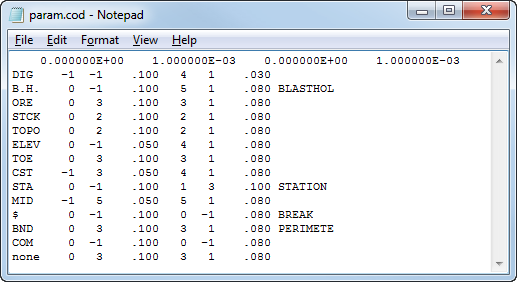
Survey Parameter File (param.cod)
Use -p filename2 to set the parameter code file (i.e., "PARAM.COD").
The Survey Parameter Code file is to control the display and plotting of survey data by data types. This file allows data to be processed and/or displayed in accordance with its point code. A four-character point code is used to identify each data type. Each point code will have a set of parameters specified for it. Multiple parameter files are allowed, but only one at a time is used. A parameter file may contain specifications for up to 500 different point codes.
For each point code, some specifications are needed on whether to treat the data as part of a string (i.e., bench toes) or as point data (i.e., blastholes).
The first line of a parameter file contains: Minimum Easting, Easting precision, Minimum Northing, and Northing precision.
Each line thereafter contains: Point code, Linetype, Pen# for line, Size of dash pattern, Symbol Number, Pen# for Symbol, Size of Symbol, and Keyword and/or Comments, if applicable.
String data will have a defined linetype; linetype should be suppressed for point data. Point data will have a defined symbol number; it is optional to define a symbol number for string data. A linetype or symbol number is suppressed for a point code by setting the pen number to a -1.
DTB Usage
Examples of the four different ways of running this program are shown below.
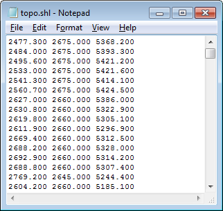
From the command line, use the following syntax to create a shell (.shl) file from survey point data.
dtb.exe +B -I -p PARAM.COD -s topo.srv -o topo.shl -F S -a
The "+B" switch tells DTB to not cross breaklines (default), "-I" to output the surface within the boundary (default), "-F" switch for type of output format (followed by the output type; "S" = shell format), and "-a" for ASCII format.
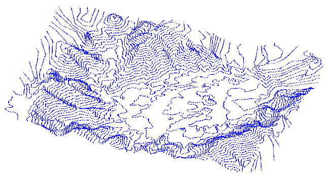
Input is "topo.srv" is displayed below (as displayed in MS3D, for illustrative purposes):
Since the syntax had the "-a" switch, the resulting output file created by DTB is an ASCII file.
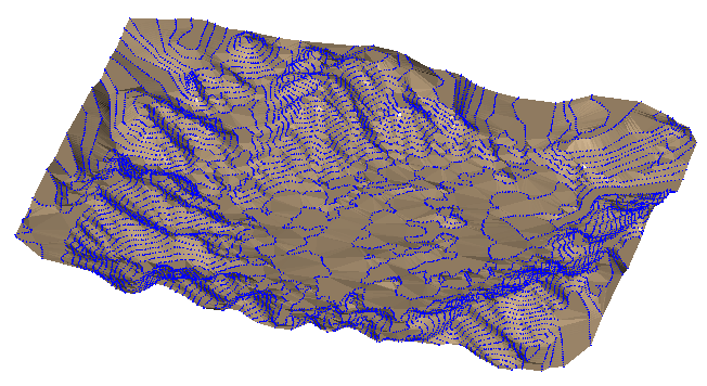
As a visual aid, the surface created by DTB is shown below in brown with the initial survey file points shown in blue.
You can run DTB interactively without the command line syntax. Simply execute the program and answer a series of questions.
c:\myproject>dtb.exe
Reading data from disk ...
Enter name for a file with control data-> param.cod
Enter name for a file with survey data-> topo.srv
Enter name for output file-> output.shl
Enter type of output information you want to have
(p - PLOT file, e - EDGES, t - TRIANGLES, s - SHELL format) -> s
SHELL
done
Data Validation ... done
Triangulation complete!
Writing data on disk ... done
Running times for program modules for 12795 points:
----------------------------------------------------
Reading Control File 0 ms
Reading Survey File 47 ms
Triangulating 47 ms
Writing surface 47 ms
OK.
As seen above in the interactive mode, you enter all information in response to questions provided by DTB. You can prepare a response file that contains the answers to those questions, and then pipe this file into the executable, dtb.exe.
Below is an example response file, called "answers".
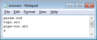
At the command line, use the following syntax to create the output file, "pipe-out.shl".
c:\myproject>dtb.exe < answers
Prepare a run file that contains all of the responses and options that the program needs in order to execute. Use the "-h" switch to view the run file setup options.
Example run file:
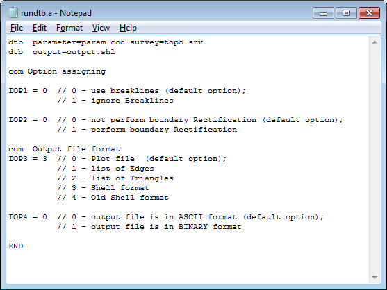
At the command line, use the following syntax to use DTB with a run file to create the output file, "output.shl".
c:\myproject>dtb.exe -f rundtb.a
NOTE: When running MSBasis programs from the command line, you can use either -f or /f between the program name and the run file name. DTB recognized only the -f option.