UNION is the engine used in solid-solid intersection. It is also used for finding holes and edges in solids as well as self-intersections, disassembling a shell consisting of many solids or surfaces into pieces, and for volume calculations.
The syntax for using UNION from the command line is described below, as well as examples that demonstrate how to use a few of the options.
Use the syntax, union -h to display this help:
|
SOLID MODELLING UTILITY
-i<1|2> file Input shell file with solids/surfaces for a group 1 or 2. There can be many input files in each group. -it<1|2> file Input ASCII triangle 3D file with solids/surfaces for a group 1 or 2. There can be many input files in each group. -ib<1|2> file Input binary shell file with solids/surfaces for a group 1 or 2. There can be many input files in each group. -o<1|2> <stream> file Output stream. It consists of one (for survey data) or three characters (for shell data) to set OPERATION, TYPE and MODE. Only OPERATION is needed to output survey data.
OPERATION Defines action to perform:
OPERATIONS TO PRODUCE SHELL DATA. i Get internal pieces of intersections. e Get external pieces of intersections. c Get co-planar pieces of intersections. I Get all but internal pieces of intersections. E Get all but external pieces of intersections. C Get all but co-planar pieces of intersections. a Get all pieces broken at intersections. x Get intersected data*. t Get not intersected data*. n Get intersection of solids. u Get union of solids. 1 Get difference 1 - 2 of solids. 2 Get difference 2 - 1 of solids. f Split at self-intersections. p Get patches. z Decimate solids. Z De-spike solids. s Report self-intersections. b Disassembly solids. X Explode solids. m Minimize shell. o Close openings. d Show duplicate triangles. l Delete duplicate triangles. q Delete all duplicate triangles.
OPERATIONS TO PRODUCE VOLUME. v Report volume.
OPERATIONS TO PRODUCE SURVEY DATA. g Show edges of surfaces. n Show areas with unresolvable inconsistent triangle normals. v Validate integrity of surfaces. p Show intersection polygons. r Show raw intersection polygons.
TYPE Filters data on certain criteria: s Solid. h Solids with openings*. f Surfaces*. o Solids and solids with openings*. a All data: solids and surfaces*.
MODE Define the way the data is output: n None: no output. s Singular: write everything in one file. m Multiple: write pieces with the same attribute in same file. p Parts: write unconnected pieces in separate files. filename File name or file name prefix (for multiple mode output) to write in.
ADDITIONAL OPTIONS.
-area Compute area.
-vec Keep original direction of triangles' normal vectors.
-center Compute center of mass.
-dec val Switch triangle decimation on and set maximal tolerance for co-planar and co-linear offset.
-f<0|1> Set triangle filter for self-intersection operations 'f' (split at self-intersections) and 's' (report self-intersections). 0 - No filter (default option). Check intersections between all triangles in the input group. 1 - Shell filter. Check intersections only between triangles in the same shell file (effective with options '-merge 0' and '-merge 1'.
-despike val Set tolerance for de-spiking.
-self val Tolerance for reporting self-intersected triangles.
-merge val Re-arrange solids within the same group by: 0 - keeping all solids separate (default). 1 - merging solids with the same attributes. 2 - merging all solids.
-dat path Define a directory path for input and output files.
* Option is currently disabled. _____________________________________________________________ UNION ver 8.8 (MS3D TL) Copyright (C) 2014 Leica Geosystems.
|
UNION is used for finding holes and edges in solids as well as self-intersections, disassembling a shell consisting of many solids or surfaces into pieces, and for volume calculations.
Use the syntax, union /h or union -v to display this command line usage information:
|
Usage: union [-i<1|2> file]... [-it<1|2> file]... [-ib<1|2> file]... [-o<1|2> <stream> file]... [-dat path] [-dec val] [-despike val] [-self dir] [-merge val] [-f<0|1> ] [-area ] [-center ] [-d ]
Example: union.exe -i1 solid_11.shl -it1 solid_12.3d -i2 solids_2.shl -o1 uss solid_union.shl -dat "c:\my data" Get a union between two groups of solids where group 1 includes solids from shell file solid_11.shl and .3D file solid_12.3d and group 2 includes shell file solid_2.shl. All input files and the result file solid_union.shl are stored in folder "c:\my data". Use option -h for more information. |
Examples using UNION from the command line:
In this section are simple examples for using union from the command line. The examples shown below use simple shapes and perform one operation at a time. Keep in mind that Union can be run with multiple operations at once and it will take almost the same amount of time to execute.
-
Example 1 - Return the Union or the Intersection of Solids
-
Example 2 - Get the Difference Between Solids
-
Example 3 - Return ALL components (all at one time)
The basic command line sequence when running union is:
union.exe <designate type of input files> <input filenames> <designate output files> <operation, type, mode> <output filesnames> <other options>
The input files must exist in the local working directory, and the output file(s) will be created in the same directory. The images shown in these examples use the MS3D viewer are as a visualization aid and for illustration. Union uses .shl or .3d files, not .msr files.
This example illustrates how to create a solid based on the union or the intersection between solids.
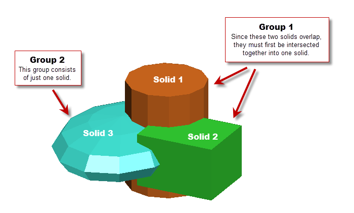
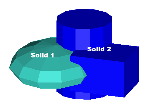
We start with 3 solids that intersect one another as illustrated in the image below (solid1.shl, solid2.shl and solid3.shl.); two of the solids are in Group 1 and one of the solids is in Group 2. Because the two solids in Group 1 overlap one another, they must first be merged into one solid using the "Return Union of Solids" option.
|
IMPORTANT NOTE: Multiple solids can be used in each group, but within a group, the solids cannot overlap each other. If the objects in a group intersect or overlap each other, you must first use the "Get union of solids" option to merge the overlapping solids into one solid. This is because union interprets such overlaps of solids in the same group as self-intersections. |
Return the Union of Solids
Using union from the command line, the syntax for the "Get union of solids" option is used to merge Solid 1 (solid1.shl) with Solid 2 (solid2.shl).
union.exe -I1 solid1.shl -I2 solid2.shl -o1 uss solid12.shl
This syntax is:
-
union.exe = the program name
-
-I1 = designates input file 1
-
solid1.shl = the filename of shell file 1
-
-I2 = designates input file 2
-
solid2.shl = the filename of shell file 2
-
-o1 = designates output file 1
-
uss = Operation, Type, and Mode. Operation u = "Get union of solids", Type s = "solid", Mode s = "Singular: writing everything in one file".
-
solid12.shl = the output filename
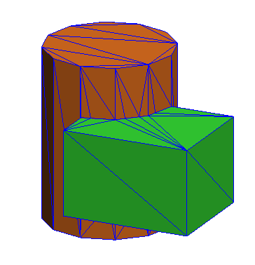
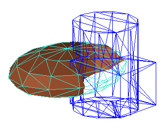
The result from this operation is illustrated below in the blue wireframe ("solid12.shl"). The original solids are shown in brown and green.
Return the Intersection of Solids
Once the intersecting solids in Group 1 have been merged into one solid, that new solid (solid12.shl) can be intersected with Solid 3 (solid3.shl) to create a solid from the part where the two solids overlap.
union.exe -I1 solid12.shl -I2 solid3.shl -o1 nss intersection_solid.shl
This syntax is:
-
union.exe = the program name
-
-I1 = designates input file 1
-
solid12.shl = the filename of shell file created in Step 1 above.
-
-I2 = designates input file 2
-
solid2.shl = the filename of shell file 2
-
-o1 = designates output file1
-
nss = Operation, Type, and Mode. Operation n = "Get intersection of solids", Type s = "solid", Mode s = "Singular: writing everything in one file".
-
intersection_solid.shl = the output filename
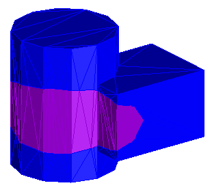
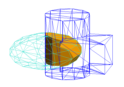
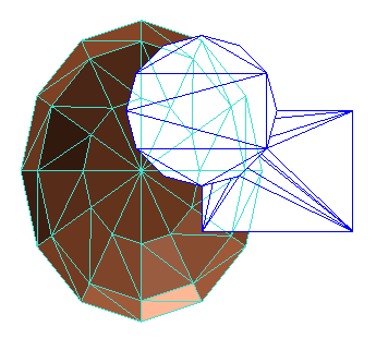
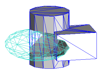
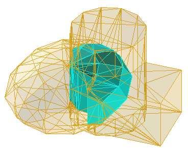
The result from this operation, intersection_solid.shl is shown in the image below as the orange solid created in the intersection of solid12.shl (in blue wireframe) with solid3.shl (in light bluegreen wireframe).
Alternatively, you can create the intersection by generating two surfaces which then can be merged to create a solid in another step (below). The command line syntax is:
union.exe -I1 solid12.shl -I2 solid3.shl -o1 iss output12.shl -o2 iss output3.shl
This syntax is:
-
union.exe = the program name
-
-I1 = designates input file 1
- solid12.shl = the name of shell file created in Step 1 above.
-
-I2 = designates input file 2
-
solid3.shl = the name of shell file 2
-
-o1 = designates output file 1
-
iss = Operation, Type, and Mode. Operation i = "Get internal pieces of intersections", Type s = "solid", Mode s = "Singular: writing everything in one file".
-
output12.shl = the first output filename which is of the surface created on the surface of the first input shell file (solid12.shl) within the boundary of the second input file (solid3.shl).
-
-o2 = designates output file 2
-
iss - Operation, Type, and Mode. Same as above.
-
output3.shl = the second output filename which is the surface created on the surface of the second input shell file (solid3.shl) within the boundary of the first input file (solid12.shl).
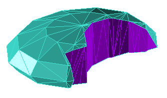
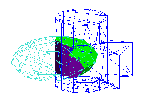
The results from the above procedure are illustrated below. The input files, solid12.shl and solid3.shl are shown in wireframe. The output files are two separate surfaces; output12.shl is shown in purple and output3.shl is shown in lime green.
Next, merge the two output surfaces (output12.shl and output3.shl) shown above in purple and limegreen to create a solid.
union.exe -I1 output12.shl I1 output3.shl -O1 mss merged_surfaces.shl
This syntax is:
-
union.exe = the program name
-
-I1 = designates input file group 1
- output12.shl = the name of shell file created just above
-
-I1 = input file. Note this is also in "group 1"
-
output3.shl = the name of second shell file in group 1
-
-o1 = designates output file 1
-
mss = Operation, Type, and Mode. Operation m = "minimize shell", Type s = "solid", Mode s = "Singular: writing everything in one file"
-
merged_surfaces.shl = the output from merging both of the input files together
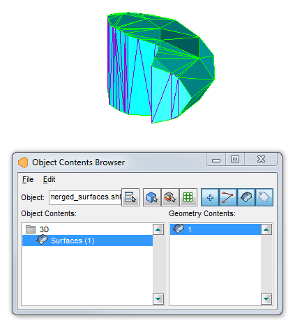
The results from this last procedure are illustrated below. The input files, output12.shl and outupt3.shl are shown in wireframe (purple and limegreen), and the one output file, "merged_surfaces.shl" is shown in solid cyan blue. In this case, in the command line syntax the two input files are considered to be part of the same "group" and the "minimize" ("m") operation option is used to join the two surfaces together. This output file is a single closed solid [verified in MS3D using the Object Contents Browser (OCB)].
Using the solids from the first example, the following shows how to create solids that are the difference between Solid 12 (solid12.shl) and Solid 3 (solid3.shl).
To get the results of Solid 1 (file, solid3.shl) minus the portion in Solid 2 (file, solid12.shl), use the following syntax:
union.exe -I1 solid3.shl -I2 solid12.shl -O1 1ss output1-2.shl
This syntax is:
-
union.exe = the program name
-
-I1 = designates input file 1
- solid3.shl = the name of the first input shell file
-
-I2 = designates input file 2
-
solid12.shl = the name of the shell file 2, created in Step 1 in the first example.
-
-o1 = designates output file 1
-
1ss = Operation, Type, and Mode. Operation 1 = "Get difference 1 - 2 of solids", Type s = "solid", Mode s = "Singular: writing everything in one file"
-
output1-2.shl = the output filename
The results from the above procedure are illustrated in the images below. The input files are shown in wireframe, and the output resulting solid is shown with brown faces.
|
Oblique view.
|
Plan view (view downward, -90°)
|
To get the results of Solid 2 (file, solid12.shl) minus the portion in Solid 1 (file, solid3.shl), use the following syntax:
union.exe -I1 solid3.shl -I2 solid12.shl -O1 2ss output2-1.shl
This syntax is:
-
union.exe = the program name
-
-I1 = designates input file 1
- solid3.shl = the name of the first input shell file
-
-I2 = designates input file 2
-
solid12.shl = the name of the shell file 2, created in Step 1 in the first example.
-
-O1 = designates output file 1
-
2ss = Operation, Type, and Mode. Operation 2 = "Get difference 2 - 1 of solids", Type s = "solid", Mode s = "Singular: writing everything in one file"
-
output2-1.shl = the output filename
The results from the above procedure are illustrated in the images below. The input files are shown in wireframe, and the output resulting solid is shown in gray.
|
Oblique view.
|
Plan view (view downward, -90°)
|
This example shows how to output all of the components using the same two solids; Solid 1 (file, solid3.shl) and Solid 2 (file, solid12.shl). The "union" and "intersection" options will create solids, and the "internal" and "external" options will create surfaces (open solids).
union.exe -I1 solid3.shl -I2 solid12.shl -O1 iss internal1.shl -O1 ess external1.shl -O1 nss intersection.shl -O1 uss union.shl -O2 iss internal2.shl -O2 ess external2.shl
This syntax is:
-
union.exe = the program name
-
-I1 = designates input file 1 (solid3.shl = Solid 1)
- solid3.shl = the name of the first input shell file
-
-I2 = designates input file 2 (solid12.shl = Solid 2)
-
solid12.shl = the name of the shell file 2, created in Step 1 in the first example.
-
-O1 = designates output file based on Solid 1 (input file, solid3.shl)
-
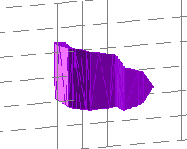
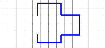
iss = Operation, Type, and Mode. Operation i = "Get the internal pieces of intersections", Type s = "solid", Mode s = "Singular: writing everything in one file"
-
internal1.shl = this is the output filename for the piece of solid3.shl that occurs within solid12.shl
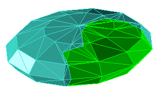
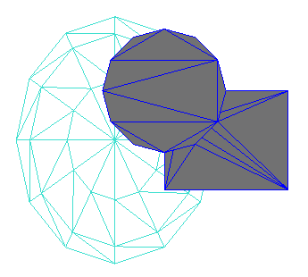
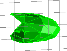
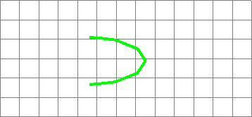
The resulting output is shown below in 3D on the left and in 2D on the right (the MS3D edit grid is shown for reference):
|
|
|
-
-O1 = designates output file based on Solid 1 (input file, solid3.shl)
-
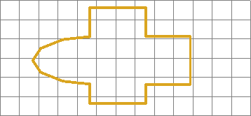
ess = Operation, Type, and Mode. Operation i = "Get the external pieces of intersections", Type s = "solid", Mode s = "Singular: writing everything in one file"
-
external1.shl = this is the output file name for the piece of solid3.shl that occurs external to (or outside of) solid12.shl
The resulting output is shown below in 3D on the left and in 2D on the right (the MS3D edit grid is shown for reference):
|
|
|

-
-O1 = designates output file based on Solid 1 (input file, solid3.shl). However using the "intersection" operation option (next entry below), in this example using "-O1" or "-O2", the result will be the same.
-
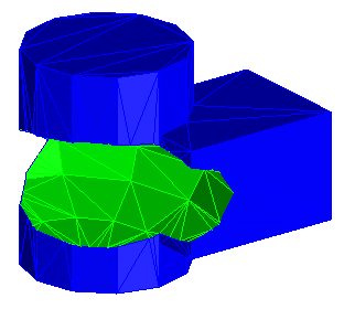
nss = Operation, Type, and Mode. Operation n = "Get the intersection of solids", Type s = "solid", Mode s = "Singular: writing everything in one file"
-
intersection.shl = this is the output file name for the solid created by the intersection of solid3.shl and solid12.shl
The resulting output is shown below in 3D on the left and in 2D on the right (the MS3D edit grid is shown for reference):
|
|
|
-
-O1 = designates output file based on Solid 1 (input file, solid3.shl). However using the "union" operation option (next entry below), in this example using "-O1" or "-O2", the result will be the same.
-
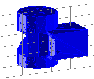
uss = Operation, Type, and Mode. Operation n = "Get the union of solids", Type s = "solid", Mode s = "Singular: writing everything in one file"
-
union.shl = this is the output file name for the solid created by the union of solid3.shl and solid12.shl
The resulting output is shown below in 3D on the left and in 2D on the right (the MS3D edit grid is shown for reference):
|
|
|
-
-O2 = designates output file based on Solid 2 (input file, solid12.shl)
-
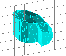
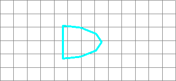
iss = Operation, Type, and Mode. Operation n = "Get internal pieces of intersections", Type s = "solid", Mode s = "Singular: writing everything in one file"
-
internal2.shl = this is the output file name for the piece of solid12.shl that occurs within solid3.shl
The resulting output is shown below in 3D on the left and in 2D on the right (the MS3D edit grid is shown for reference):
|
|
|

-
-O2 = designates output file based on Solid 2 (input file, solid12.shl)
-
ess = Operation, Type, and Mode. Operation n = "Get external pieces of intersections", Type s = "solid", Mode s = "Singular: writing everything in one file"
-
external2.shl = this is the output file name for the piece of solid12.shl that occurs external to (or outside of) solid3.shl
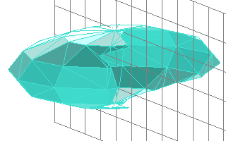
The resulting output is shown below in 3D on the left and in 2D on the right (the MS3D edit grid is shown for reference):
|
|
|
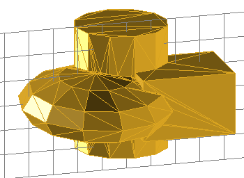
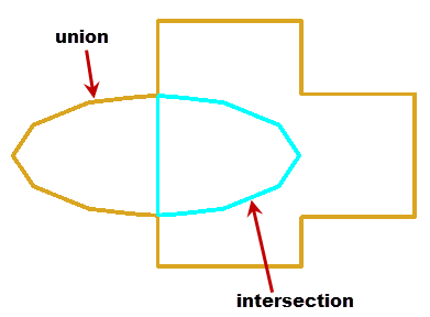
In this example, union created 6 components from the 2 solids (solid3.shl and solid12.shl). The images below show the pieces relative to one another.
These images (from MS3D) illustrate the results from the union and the intersection of the solids. These options create solids; the "intersection" between the solids is shown as cyan blue solid within the outer "union" solid, displayed in goldenrod brown.
|
3D oblique view
|
2D Cross sectional view
|
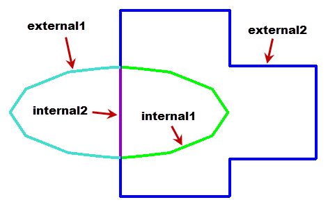
The remaining 4 parts are surfaces that were created using the "get internal pieces" and "get external pieces" options.
Putting all 4 surfaces together, this shows a 2D cross sectional view:
The following images (from MS3D) illustrate Solid 1 with the two internal parts, and Solid 2 with the same two internal parts in shown in 3D oblique views.
|
external1 and internal1:
|
external1 and internal2:
|
|
external2 and internal2:
|
external2 and internal1:
|