SGR is used for surface gridding and volume calculation. This program calculates 2D grids of triangulated surfaces and calculates volumes between two surfaces using gridding logic. There are three main working modes to this program; gridding a triangulated surface, simple cut and fill volumes between two surfaces, and cut and fill partials and level volumes between two surfaces.
Comparing the results from SGR versus checking the same volumes in MS3D, there may be a difference in the absolute numbers that is most likely due gridding vs analytical volume calculation. This is similar to digital and analog: the quality of your result is based on the level of sampling (gridding).
There are 3 main working modes for SGR
The syntax for using SGR from the command line:
|
SURFACE GRIDDING AND VOLUME CALCULATION UTILITY -topshl file Input shell file containing upper surface or a single surface to grid. -botshl file Input shell file containing lower surface. This file is used for volume and partials calculations between the upper and lower surfaces. -limitshl file Input shell file containing limiting surface. -bench file Input file containing a list of benches for partials calculations. Contains bench toe elevations arranged in descending order one entry per line. -prt file Output cutting and filling partials. Program will create two files (file.cut and file.fil) coded in m659v1 program format and a file.vol with volumes per bench. -grid file Output file with a grid coded in m610v1 program format. -vol file Output file with cut and fill volumes between upper and lower surfaces. -xmin/-ymin X/Y coordinates of the origin of the grid. -nx/-ny Number of columns/rows in a grid. -dx/-dy Width/height of a cell. -sbx/-sby Number of sub-columns/sub-rows in a cell. -hx/-hy X/Y coordinates of hinge point. -dip/-azim Dip/azimuth of bench inclination (degrees). Dip - negative is down, Azimuth measured from North clockwise. -cell method Method for setting cell value. This can be: average (default), lowest, highest. in Megabytes. Default size is 10. -mem Maximal allowed size of allocated memory in Megabytes. Default size is 10. -cover Program defines -xmin,-ymin, -nx and -ny parameters to cover all surface(s) with the grid. -extend Program defines -nx and -ny parameters to cover surface(s), starting from the user specified origin. -feet Report imperial measurements. -real If used with -grid option: output real co-ordinates rather than indices. If used with -prt option: output partials as percents in real format. -dat dir Define a directory for input and output files. -tmp dir Define a directory for intermediate files. -d Debugging mode. Output intermediate information. -e Economy mode. Program dumps out results to the disk as soon as possible to save memory. ______________________________________________________ SGR ver 1.4 (MS3D TL) Copyright (C) 2014 Leica Geosystems. |
Input Surfaces
A shell format file containing a surface (or surfaces with no overlaps in 2D) is passed as input and a grid file is returned as output. The top (upper) surface is defined using the "-topshl" command in front of the .shl filename, and the bottom (lower) surface is defined using the "-botshl" command in front of the .shl filename.
Notes relating to the Command Line arguments, sgr -v
Releasing system resources ... done
Usage: sgr <-topshl file> [-botshl file] [-limitshl file]
[ -bench file] <[-grid file] | [-prt file] | [ -vol file]>
[ -xmin val] [-ymin val] [ -nx val] [ -ny val]
< -dx val> < -dy val> < -sbx val> < -sby val>
[ -hx val] [ -hy val] [ -dip val] [-azim val]
[ -mem val] [ -cover] [ -extend] [ -dat dir]
[ -tmp dir] [ -real] [ -feet] [-d] [-e] [-h]
[ -cell val]
Use option -h for more information.
-
Parameters in angle brackets < > are required. Square brackets [ ] enclose optional parameters.
-
All options are case insensitive.
-
The order in which options are typed on the command line is not important.
-
If the file to be opened already exists, that file will be overwritten without warning. Also, the program does not perform any checks to find if previous output data can be overwritten in the same program run.
-
The following pairs of options are mutually exclusive; -prt file, -vol file and -grid file
-
If you use -prt file, then the -bench file option must be specified.
-
The -real switch applies to reporting cut and fill partials (option -prt) as an addition to the -grid option.
-
If you enter incorrect command line parameters, the program produces a relevant warning and stops.
Such as:


The Volumes and Partials are binned by Cut and Fill (see 2nd mode for Cut and Fill definition), and 3 files are created on output
(-prt).
1. file.'cut' - Contains 3D partials representing the Cut volume.
2. file.'fil' - Contains 3D partials representing the Fill volume.
3. file.'vol' - Contains a report of Cut and Fill volumes by bench.
Files '.cut' and '.fil' are created in the MSBasis m659v1 program file format (refer to the MSBasis program documentation, in m600.pdf). The file '.vol' is in free format.
Using a limiting surface
Normally the program defines an area where grids, volumes or partials are calculated as a region that is an intersection of top and bottom surfaces and specified grid. This region can be further corrected by using a special 'limiting' surface. Limiting is a shell file that can include one or more 2D surfaces.
Format of the Bench File
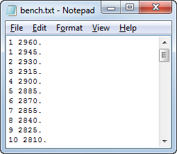
The bench file is used by the program for partials and level volume calculations. It defines a reference and elevation for the toe of each bench. The first line refers to the elevation of the crest of the top bench. The format for the -bench file option is: the first number is bench number, the second number is bench elevation (shown in the example below). If the data is not in the correct format, the following error message will be displayed, "No data found or incorrect data format in bench file."
The file can consist of one or more free format lines of the following structure:
<Bench ID> <First Bench Crest Elevation >
<Bench ID> <First Bench Toe Elevation >
<Bench ID> <Second Bench Toe Elevation >
.
.
<Bench ID> < Last Bench Toe Elevation >
Notes on file format structure:
-
Bench elevations are floating point numbers sorted in descending order.
-
Bench IDs are integer references.
-
There is no limit on the number of benches.
-
Benches can have different heights.
-
Empty lines are allowed throughout the file.
Example bench file:
Grid parameters
The -xmin/-ymin, -nx/-ny, -dx/-dy, -sbx/-sby key word options are used in calculating the grid. The values used, along with these key words, are the project’s extents and block size.
Modes Usage Examples:
A shell format file containing a surface (or surfaces with no overlaps in 2D) is passed as input and a grid file is returned as output. The output grid file is formatted in MSBasis m610v1 format (refer to the MSBasis documentation which is accessed from the Help Menu in MS3D).
The switch controlling the input file is -topshl, and for the output grid file is -grid.
The setup of the 2D Grid is controlled by the following command parameters. There are essentially 3 ways these can be specified:
-
All Grid parameters are defined by the user. These are:
1. X, Y coordinates of the origin of the grid -xmin/-ymin
2. The number of columns and rows in the grid -nx/-ny
3. The width and length of a cell -dx/-dy
- The program defines the number of cells in X and Y to extend the grid to cover the surface from a specified origin and cell size (1 and 3 just above). This is invoked with the -extend switch.
-
The program automatically covers the surface with a grid using a specified cell size (3 just above). This is invoked with the -cover switch.
When performing the gridding, SGR splits each cell into a number of sub-cells (in X and Y) and determines an intersection between the surface and a vertical ray going from the center of the sub-cell. This subdivision is controlled by the 2 parameters: -sbx/-sby. The elevations calculated for all sub-cells in the cell are averaged and a single value is assigned to the cell. The accuracy of the final elevation depends on the parent cell size, the geometry of the surface and the number of sub-cell calculations performed.
Each cell contains a final calculated elevation if at least 50% of the surface covers it. This means that for cases where holes exist, or embayments are present, the grid will contain no values.
The grid file that is output can be represented in 2 ways. The default format is MSBasis m610v1 format which tracks the column and row reference numbers of each cell, along with the elevation (for information about program, m610v1 refer to the MSBasis documentation which is accessed from the Help Menu in MS3D). If the -real switch is used, the format is X, Y, Z rather than Column, Row, Z for each cell.
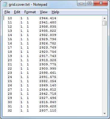
Syntax for using the "-cover" option
sgr.exe -topshl topo.shl -grid grid.cover.txt -dx 20 -dy 20 -sbx 1 -sby 1 -cover
The file, "grid.cover.txt" file is created:
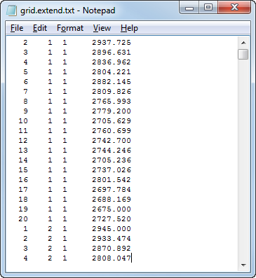
Syntax for using the "-extend" option
sgr.exe -topshl topo.shl -grid grid.extend.txt -xmin 1000 -ymin 4000 -dx 150 -dy 125 -sbx 1
-sby 1 -extend
The file, "grid.extend.txt" file is created:
This mode uses the same setup as discussed above, except there are two surfaces as input rather than one surface. This mode is used to find the volume between the surfaces (.shl files); a top surface -topshl and a bottom surface are input -botshl and the -vol switch is invoked rather than -grid.
The upper and lower surface are gridded and total volumes between them are calculated where they overlap. If there is at least 50% of both surfaces covering a cell, a volume is calculated between them. Since the surfaces may intersect any number of times in 3D, the volume is partitioned into Cut and Fill bins. Cut is defined as volume where the surface in -topshl is above the surface in -botshl, and Fill where the surface in -topshl is below the surface in -botshl.
While this volume calculation is fast, it may not be accurate enough if the cell size is large and higher resolution is needed when representing the overlap between the 2 surfaces (currently using the 50% rule). If more accuracy is needed, the next mode to be discussed should be used.
The volumes calculated, are returned in a free format ASCII file specified with the -vol command.
Syntax for calculating Cut and Fill volumes between two Surfaces
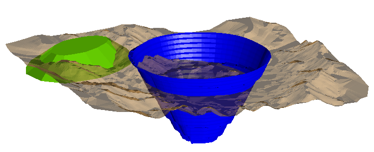
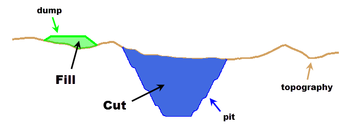
This example illustrates the use of SGR to calculate the cut and fill volumes for a pit and a dump. Fill volumes are reported as a negative number.
In the image below, both the pit surface (in blue) and the dump surface (in green) pierce through a topographic surface (light brown). In the image below the topography surface is displayed with transparency turned on, thus enabling you to see the portion of the dump or pit below it.
To calculate the volume between these surfaces and the topographic surface, sgr is run twice (once for the pit and again for the dump) from the command line to create the ASCII text files containing the cut and fill volume information.
- To calculate the volume between the pit and topography, use the following syntax. Notice in this case topography (topo.shl) is the top surface, and the pit (pit.shl) is the bottom surface:
sgr.exe –topshl topo.shl –botshl pit.shl –bench bench.txt –xmin 1000 -ymin 4000 –nx 150 –ny 125 –dx 20 –dy 20 –sbx 1 –sby 1 –vol pit-and-topo-volume.txt
- To calculate the volume between the dump and topography, use the following syntax. Notice in this case the dump (dump.shl)is the top surface, and topography (topo.shl) is the bottom surface:
sgr.exe –topshl dump.shl –botshl topo.shl –bench bench.txt –xmin 1000 -ymin 4000 –nx 150 –ny 125 –dx 20 –dy 20 –sbx 1 –sby 1 –vol dump-and-topo-volume.txt
In either syntax, the -xmin/-ymin, -nx/-ny, -dx/-dy and -sbx/-sby define the grid size used.
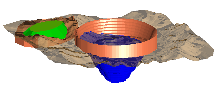
In the resulting cut & fill values, the negative "fill" volumes are calculated for the portion of the pit that occurs above the topography, and for the portion of the dump portion that occurs below the topography. This is illustrated below; the "fill" portions are shown in orange in a 3D view.
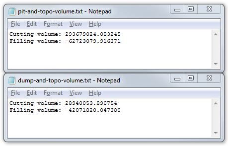
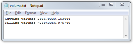
The results output from SGR are:
Whereas, comparing a "final" surface (merged dump, pit and topo = merged.shl, shown below) with original topography, the volumes reported by SGR will reflect the cut (pit) and fill (dump) volumes. 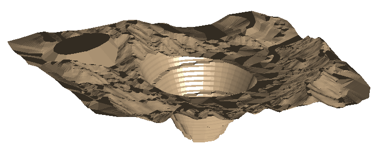
In 2D cross section, this scenario is illustrated below (the various parts are shown in different colors for illustrative purposes).
sgr.exe –topshl merged.shl –botshl topo.shl –bench bench.txt –xmin 1000 -ymin 4000 –nx 150 –ny 125 –dx 20 –dy 20 –sbx 1 –sby 1 –vol volume.txt
The third mode returns a more detailed representation of the volume between the 2 surfaces than Mode 2.
The volume is partitioned into levels and accurately determines the percentages of 3D cells (partials) that fall within the levels and between the surfaces. The surfaces are input as before -topshl and -botshl, and the grid setup is the same as above.
The additional information needed is to specify where the levels sit in 3D space. This is detailed in a bench file -bench which contains the list of bench toes, as well as a the crest of the top bench. The spacing between the toes determines the height of each bench (see Format of Bench File above). The output is returned in 3 files using the -prt switch.
If the volumes are to be calculated within an inclined bench system, an additional set of parameters must be specified. The inclination orientation is determined by the origin of the hinge point -hx/-hy, the dip direction of inclination -azim (measured in degrees clockwise from North), and the dip angle -dip (in degrees with -ve referring to the down direction).
To determine the level volumes and partials, elevations for each sub-cell are compared with the corresponding sub-cell of the second surface. Comparing these elevation differences at the sub-cell level, provides an accurate representation of where the surfaces overlap in 2D and 3D, as well as the level volumes between them. To calculate the partials, a set of columns are partitioned into 3D cells by level, with each containing a single 2D grid cell. The sub-cell elevations for each surface, are then used to determine the makeup of the 3D cells within each column. For example, if a 3D cell is fully contained between the surfaces it gets 100%, if completely outside 0%, otherwise some value in between.
The volumes and partials are binned by Cut and Fill (see Mode 2 for Cut and Fill definition); 3 files are created on output -prt.
-
File.'cut' - Contains 3D partials representing the Cut volume.
-
File.'fil' - Contains 3D partials representing the Fill volume.
-
File.'vol' - Contains a report of Cut and Fill volumes by bench. The file '.vol' is in free format.
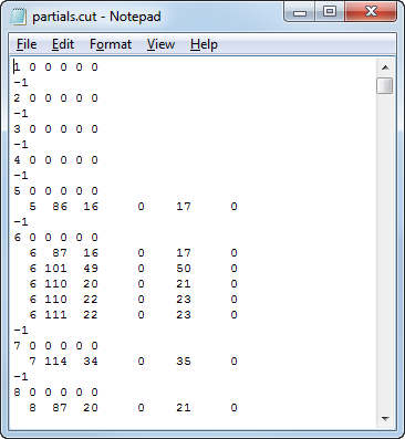
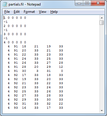
Files '.cut' and '.fil' are created in the MSBasis program, m659v1 file format. (refer to the MSBasis documentation which is accessed from the Help Menu in MS3D).
Example
Using the surfaces from above, topography (topo.shl) and the merged surface with the dump, the pit and topo (merged.shl), the syntax is:
sgr.exe -topshl topo.shl -botshl merged.shl -bench bench.txt -xmin 1000 -ymin 4000 -nx 150 -ny 125 -dx 20 -dy 20 -sbx 1 -sby 1 -prt partials
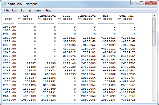
The cutting partials file, the filling partials file and the volume partials file are created:
|
Cutting partials file:
|
Filling partials file:
|
|
Volume partials file:
|