VOXEL uses one or more solids from an input shell file and a block model definition to calculate what percentage of each block in the block model is filled with the solids. The result is output in a standard MineSight "partials" file.
The syntax for using VOXEL from the command line is described below. Only the "-real" and "-rot [1|2|3]" options are optional.
Use either the -h, /h or --h option syntax at the command line to display this program's syntax information:
|
CALCULATE BLOCK PARTIALS FROM SOLIDS [-shl file] [-prt file] [-bench file] – input, output and bench files [-xmin val] [-ymin val] [-zmin val] – coordinates of the minimum corner of the block model [-rot1 val] [-rot2 val] [-rot3 val] – rotation angles (degrees) of the block [-nx val] [-ny val] [-nz val] - number of blocks in x,y,z [-dx val] [-dy val] [-dz val] – size of the block [-sb val] – number of sub-blocks in a block [-real] – output partials as floating point values, otherwise integers are used. |
Use the -bench file option to input the top crest and toe elevation levels for a variable bench 3-D block model. The format for file is as follows. Use of "-nz" is required and must be the number of toes in the file.
0 100.0 <-- Crest
1 75.0 <-- First toe
...
4 0.0 <-- Last toe
Example usage of Voxel
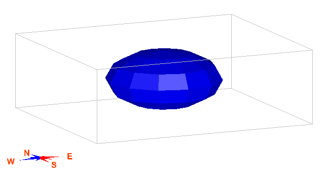
A simple shell (the blue solid as shown below in MS3D) is used to illustrate this example. In this case, Voxel is used to calculate the partials within a the shell file, "sphere". The input shell file is, "sphere.shl", and the output partials file is, "output.prt".
voxel.exe -shl sphere.shl -prt output.prt -xmin 1000 -ymin 4000 -zmin 2000 -dx 20 -dy 20 -sb 8 -nx 150 -ny 125 -nz 64
This syntax used in this example is:
|
voxel.exe |
= |
the program name |
|
-shl sphere.shl |
= |
keyword to designate input shell file, and the input shell filename |
|
-prt output.prt |
= |
keyword to designate output partials file, and the output partials filename |
|
-xmin 1000 |
= |
keyword and value that designates the block model origin in the X direction |
|
-ymin 4000 |
= |
keyword and value that designates the block model origin in the Y direction |
|
-Zmin 2000 |
= |
keyword and value that designates the block model origin in the Z direction |
|
-dx 20 |
= |
keyword and value that designates the block size in the X direction |
|
-dy 20 |
= |
keyword and value that designates the block size in the Y direction |
|
-dz 15 |
= |
keyword and value that designates the block size in the Z direction |
|
-sb 8 |
= |
keyword and value that designates the number of subblocks. To clarify, this is the number of increments to pass through a block. |
|
-nx 150 |
= |
keyword and value that designate the number of model blocks in the X direction |
|
-ny 125 |
= |
keyword and value that designate the number of model blocks in the Y direction |
|
-nz 64 |
= |
keyword and value that designate the number of model blocks in the Z direction |
The output partials file, "output.prt" contains Header Lines, Partials Lines, and Footer Lines.
The Header Line defines the range of blocks that the following partials lines cover, and is highlighted in yellow in the image below. The Header Line has the format: Bench# , Phase # (always 0), starting Column#, ending Column#, starting Row#, ending Row#, Bench#. The Footer Line begins with "-1" and contain 0's for the other columns, and is highlighted in pink in the image below. The Header and Footer Lines break up the partials records by bench.
The Partials Lines are bracketed between a Header Line and a Footer Line, and are listed in the format: Bench#, Row#, Column#, partials%, Column#, partials%, Bench#. For example, on line 2 in the file shown below (the line just below the yellow highlighted Header Line), on Bench 8, in Row 58, in Column 73 the partials value is 0%, then in Column 74 the partials value is 2%.
The Bench# is always listed in the 7th data column regardless of line type.