Correct Delaunay Triangulation (CDT) is used to correct triangulations, or more specifically it corrects:
-
Triangulated contour strings by removing flat areas.
-
Triangulations where 2-D boundary strings (with no Z value) were used to produce 3-D triangulation.
-
Triangulated grid to provide consistency in 3-D between triangulations of slightly different gridded data.
The syntax for using CDT from the command line is described below.
Use the syntax, cdt -h to display this help:
|
CORRECTING DELAUNAY TRIANGULATION -prm file Parameter shell file for contour data. -srv file Survey file with contours. -ishl file Input shell file with triangulated surface. -oshl file Output shell file with corrected surface. -dir path Define a directory with input files. -width val Maximal vertical width of a contour string. -contour Correct triangulated contour strings. -boundary Correct triangulated 2D boundary strings. -grid Correct triangulated grid. |
Use the syntax, cdt --h, cdt /h, or cdt -v to display this usage information:
|
Usage: cdt <-ishl filename> <-oshl filename> [-srv filename] [-prm filename] [-width val] [-dir path] [-contour] [-boundary] [-grid] Use option -h for more information. |
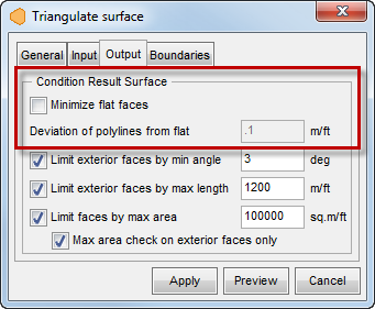
CDT functionality is similar to the "Minimize flat faces" option in the MS3D Triangulate by Dialog, as outlined in red in the image below [also refer to the MS3D documentation in file, MS3D.chm].
From MS3D:
Use the syntax below to minimize flat faces:
cdt.exe -prm param.cod -srv contours.srv -ishl BeforeSurface.shl -width 20 -oshl AfterSurface.shl
For input, CDT.exe requires:
-
Survey file containing the contours (.srv)
-
Parameter code file (param.cod) for the survey file (.cod)
-
Surface shell file (.shl) that needs to be fixed
-
You will need to specify the maximum vertical width to use; in this example a difference of 20 was used.
Output from CDT.exe is the a corrected surface .shl file.
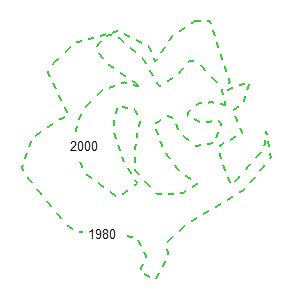
Shown below (from MS3D, in plan view) are the input contour polylines that are located on the 1980 and 2000 levels.
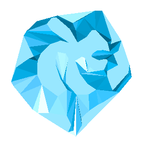
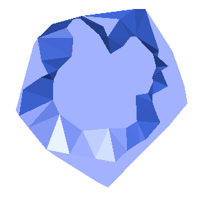
Input Surface (shown with and without the above contours); Notice the triangulation across the upper, flat surface virtually ignores some of the contour's fluctuations.
|
|
|
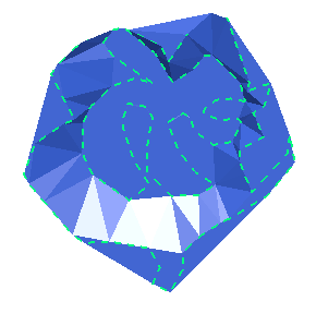
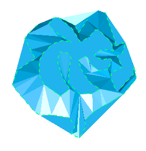
Output surface from CDT (shown with and without the above contours); Notice that the resulting upper flat surface follows the contours more accurately.
|
|
|