MSCODE.EXE is the standalone version of the MS3D drillhole coding and model coding that is run from the command line. Using MSCODE you can either directly code the model or drillholes, or output a partials file.
To display the available options for MSCODE.EXE use either -h or -v.
The syntax for using MSCODE from the command line is described below.
|
MineSight® Drillhole and Model coding Options: -h -v Display this help. -t file MSCODE template file. -i file MSCODE INI file. Use more than once to concatenate files. -o file Write partials file. Do not code model. -r Output partials in Real format. -f Output partials in Free format. (default) -a Output partials as Area Specification lines. -nn Ignore element names in the Geometry Set. -np Suppress the progress display. -q Quiet mode. ______________________________________________________ MSCODE 12.0 (build 72603-CI-83) Copyright (C) 2014 Leica Geosystems. All Rights Reserved. |
MSCODE requires the use of a "template" file or an "INI" file for input. Either file can be created using the Export option on the Model View Properties | Code Model dialog or on the Drillhole Properties | Code DH dialog in MS3D; this is discussed in further detail below, see Usage Example section. [Also refer to the MS3D help documentation, MS3D.CHM] Codes can be either integer or real (float) values.
|
NOTE: The priority of use by MSCODE is: Template file | INI file | Command line options. The -i (INI) switch can be used more than once to concatenate INI files. If any values appear more than once in the concatenated INI files, the last instance is used. A template file (-t) can be used with INI files. Any values that are in the template file than are in the INI file will be overwritten by the INI file. Any command line options that are used in the INI file will be overwritten by the command line options used to run MSCODE.EXE. |
-
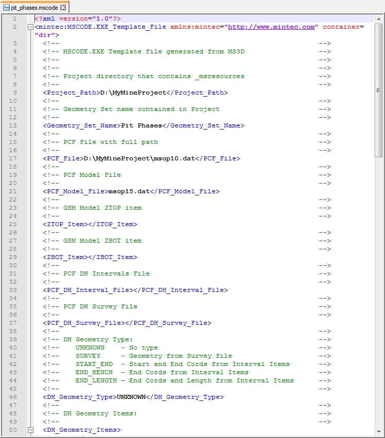
Template file: The -t <file> switch allows you to specify the template file. A template file is an XML file with the extension, ".mscode" that can be used in both Model Coding and Drillhole Coding. Contained in this file is documentation about the values that can be modified. This file can be editing in any text editor, however, we strongly recommend against editing a Template file, as that will make it unusable. Template files contain every detail and there are no default values.
An .mscode file can contains thousands of lines, such as in the example displayed below which has over 8,700 lines.
-
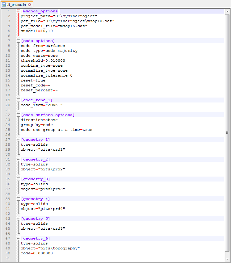
INI file: The -i <file> switch allows you to specify the INI file. An INI file is a plain-text file with the extension, ".ini" that can be used in both Model Coding and Drillhole Coding. An INI file is simple to create and can be easily written into scripts. An INI file contains configuration information; it contains default values, hence, you do not have to specify every detail in an INI file. An example .ini file is shown below, and it includes the PCF (project control file), the model file, the model item to be coded, subcell count, and the geometry and corresponding code values to be used.
-
INI File Specifications: has information regarding the specific configuration information that is contained within an INI file. This includes the syntax for filtering on model items and model range.
Use -o <file> to write the partials to the specified file rather than code the model. This option is only available when using template files that code models. Multiple sessions will overwrite, rather than append, values to the specified file. The output file is written in MSBasis program, M659V1 format [NOTE: the documentation for program M659V1 is located in %medexe%\helpdoc\M600.PDF].
Use the -r option to output percent values in the partials file as real (floating point) values. This option invokes the Free format (-f) switch.
The -f option is used to output the partials file in Free format.
The -a option is used in conjunction with the -o <file> option to create an output file in "Area Specification" file format. The output consists of the starting level, ending level, starting row, ending row, starting column, and ending column [IL1 IL2 IR1 IR2 IC1 IC2]. An "Area Specification" file is also called a "Block Definition" file. It is used in creating a compressed model file (file 15) because it defines the model area [reference in the MS3D helpdoc, go to the section, "Initialize New Project Files" found via MS Compass | PCF Editing | Project File Editor.
Use the -nn option switch to Ignore Geometry Element name grouping in the Geometry Set. In the INI file "mscode_options" section, key value "ignore_elem_names=true" has the same effect as using -nn. If "Override Code" is toggled on for the first element group in the Geometry Set, MSCODE will use the override code as the code value for all the elements contained in the object. Otherwise, MSCODE will use the code value for each element in the object.
Use the -np switch to suppress the progress display. By default, while MSCODE is running, progress meter percentiles are output to the screen. The -np option is used to avoid the list of progress percentiles.
The -q option suppresses all output except for error messages.
|
NOTE: When coding from polygons: where there are unresolved model blocks or drillhole intervals, the plane name or plane location as well as the number of unresolved blocks or intervals will be reported to the message window. Unresolved blocks or intervals occur when there is overlap of polygons with different codes. |
Usage Examples
-
Create a partials file (no model coding or drillhole coding)
-
Using the -f option to output partials in Free format (default)
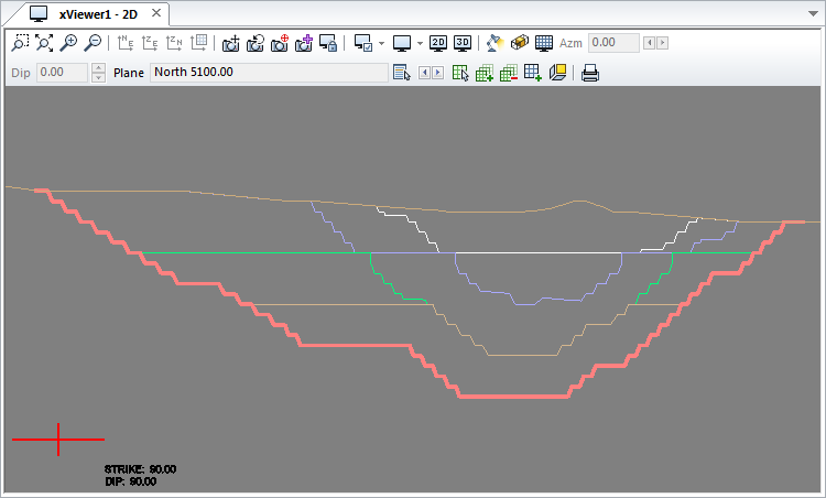
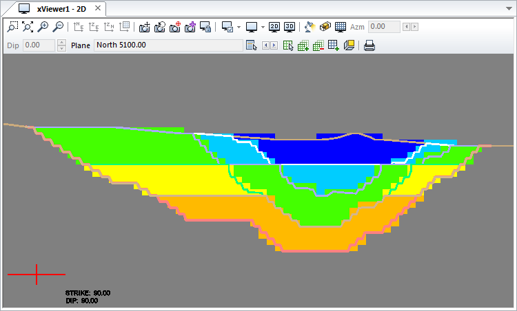
In these examples there are either 6 surfaces; 5 nested pits and original topography (in the drillhole coding example below, solids are used). The image below illustrates these surfaces as they are displayed in a 2D orthogonal cross section view in MS3D. The model item, "Zone" is displayed in gray = 0.
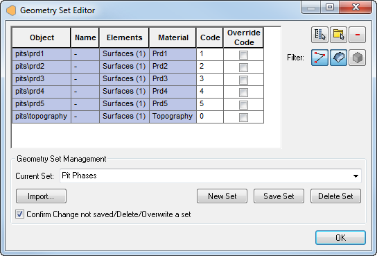
Prior to using MSCODE, either a .mscode file or an .ini file must be created as one or the other is required for input. Begin in MS3D by selecting the geometry in the Geometry Set Editor which is accessed from either the Model View Editor | Geometry tab, or the Drillhole View Properties | Code DH tab.
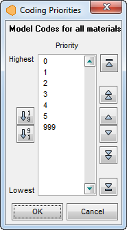
TIP: When you are using multiple solids, surfaces or polygons for coding, be sure to check the model code priority via the "Coding Priorities" dialog.
|
|
|
|
In addition to setting up the geometry to be used, you must also set up the various coding options in MS3D. Coding options are not specified on the command line. Along with the geometry set information, the selected files to be coded (model file or drillhole files), along with the coding options will also be saved to the .mscode file or .ini file (i.e., this includes Storing options such as "CODE by majority code", Code as, the Code Item, etc. If you are using surfaces to code model blocks, you must specify whether the blocks should be coded above or below the surfaces). |
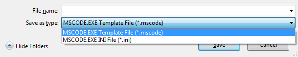
Once you are satisfied with the selected geometry and their code values, save the geometry set. In this example, the set is named, "Pit Phases". Then, in the Model View Editor | Code Model tab (or in the Drillhole View Properties | Code DH tab) click on the "Export" button to export the geometry set to either Template (.mscode) or INI (.ini) file format.
Once an .mscode or .ini file has been created, it can be used by MSCODE.
To start, the model code item "Zone" is unset. This item will be coded based on the code settings as shown in the Geometry Set Editor (see image above). Previously selected coding option were also saved to the .mscode file or .ini file along with the geometry set information. Use the syntax below (using an ".mscode" file will return the same results).
mscode.exe -i pit_phases.ini
As viewed in MS3D, below is the result from using the syntax above.
Drillhole intervals can only be coded based on solids or polygons. If you use polygons to code drillhole intervals, only those intervals within the area of influence of the plane where the polygon(s) exist will be coded.
To start, the drillhole item "Zone" is unset.
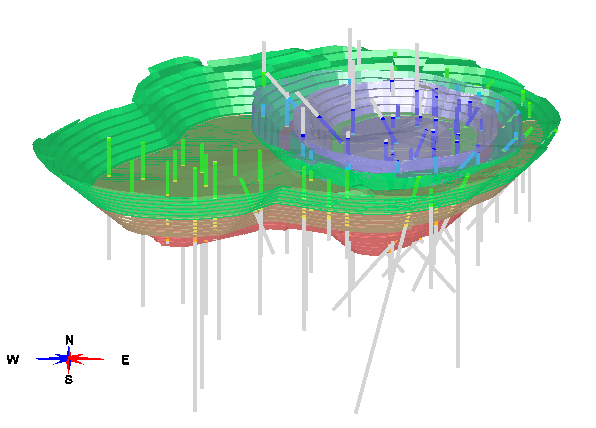
|
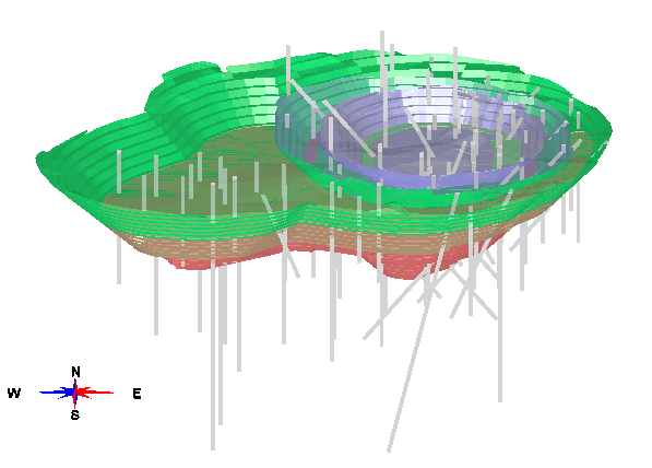
As seen in MS3D, the drillholes are displayed showing item "Zone" in gray (unset value). The drillholes pierce the 5 solids, before coding:
|
|
The drillholes shown without the solids, before coding:
|
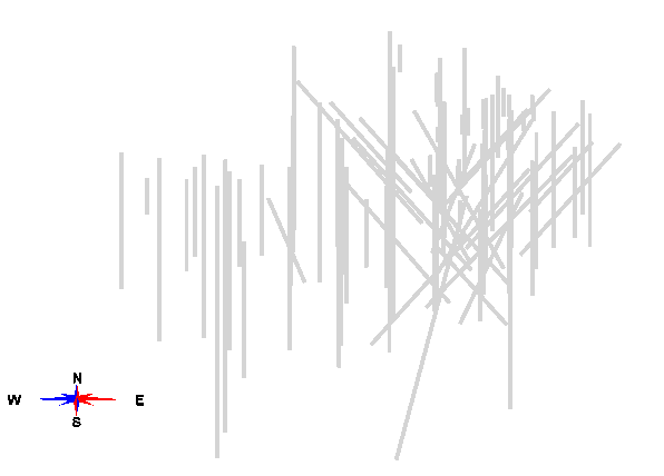
Item "Zone" will be coded based on solids geometry that is saved to "pit_phases_solids.ini". Selected coding options are also saved to the ".ini" file along with the geometry set information (using an ".mscode" file will return the same results). Use the syntax below to code the drillhole intervals.
mscode.exe -i pit_phases_solids.ini
As viewed in MS3D, below is the result after using the syntax above.
|
The drillholes pierce the 5 solids and are coded based on this geometry:
|
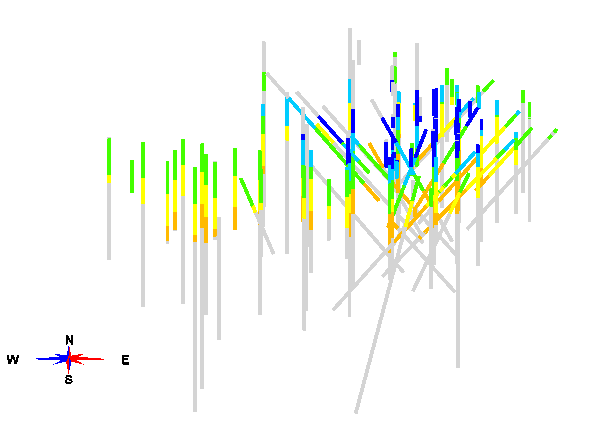
|
The drillholes shown without the solids, after coding:
|
You can use MSCODE to create a partials file. There are 3 options available; integer, real, and area specification. Again, the coding options and geometry set must be selected within MS3D and saved to either an ".ini" file or ".mscode" file for use with MSCODE on the command line.
Use the following syntax to output a partials file in Free format. Use of the "-f " switch is optional (it is the default).
mscode.exe -i pit_phases -o output.prt *OR* mscode -i pit_phases -o FreeFormat.prt -f
The Partials Files that are output using either syntax are identical:
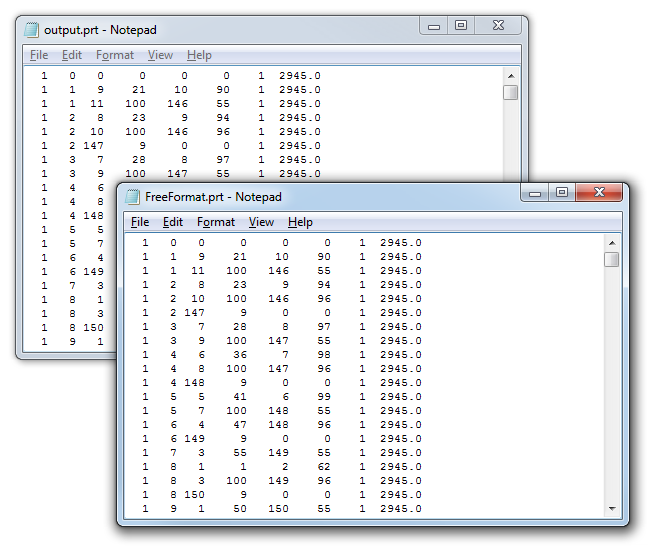
The Partials File has Header Lines, Partials Lines, and Footer Lines The Header Line defines the range of blocks that the following partials lines cover. The Header Line has the format: Bench# , Phase # (always 0), starting Column#, ending Column#, starting Row#, ending Row#, Bench#. The Footer Line begins with "-1" and contain 0's for the other columns. The Header and Footer Lines break up the partials records by bench. The Partials Lines are bracketed between a Header Line and a Footer Line, and are listed in the format: Bench#, Row#, Column#, partials%, Column#, partials%, Bench#. [see also the discussion about Partials files in the VOXEL documentation.]
Use the following syntax to output partials in real format:
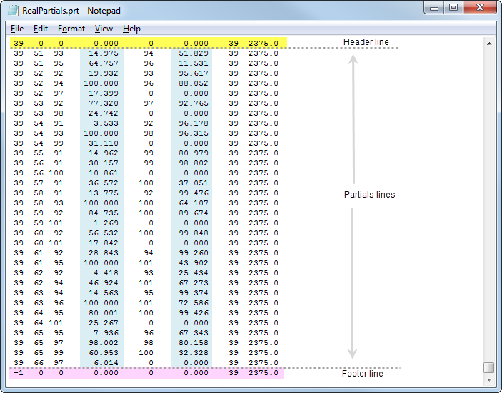
mscode.exe -i pit_phases.ini -o RealPartials.prt -r
In this case, the output partials value is a real value, not an integer. The image below shows the output using the syntax above. The header line is highlighted in yellow, the footer line in pink, and the partials lines are sandwiched between using the format, Bench#, Row#, Column#, partials%, Column#, partials%, Bench#. The partials% values are in columns highlighted in blue.
Use the following syntax to output an "area specification" type of partials file using the same ".ini" file shown above. An area specification file is used to define the model blocks that occur within a specified geometry (surface, solid, polygon).
mscode.exe -i pit_phases.ini -o AreaSpecification.prt -a
The output Area Specification file is shown below.
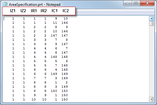
The format for an Area Specification file is: IZ1 IZ2 IR1 IR2 IC1 IC2 (as shown above).
IZ1 = Starting level number
IZ2 = Ending level number
IR1 = First row in each level IZ1 to IZ2
IR2 = Last row in each level
IC1 = First column in each row IR1 to IR2
IC2 = Last column in each row
The above Area Specification Line can be repeated as often as necessary to define all areas of interest in the model. Area specifications can overlap; however, once a level is completed, any defined row cannot be redefined. For example:
1 6 1 50 25 75
5 7 1 45 30 80
Overlap on levels 5 and 6. The result would be the largest definition for rows 1 to 45 where columns 25 to 80 would be defined.
[Also refer to the documentation for MSBasis program, M601V2 found in %medexe%\helpdoc\m600.pdf. MSBasis program documentation is also accessed from the Help Menu in MS3D].