SCLIP is used to clip strings against 3D triangulated solids or surfaces or 2D polygons/polylines (solidstring clipping utility). In particular, this program is used to spear 3D geometry objects with drillholes and code the intervals.
This complex program has eight different optional modes:
-
3D solid/string clipping (and determination of inside/outside)
-
2D polygon/string clipping (also includes determination of inside/outside)
-
self-intersection of strings within the same file
-
string validation
-
solid validation
-
string reconstruction
-
string optimization
Use the syntax, sclip -h to display this help:
|
SOLID-STRING CLIPPING UTILITY -prm file Input parameter file. -srv file Input survey file with strings to clip. -drh file Input drillhole data to clip. -bnd file Input survey file with string boundary. -shl file Input shell file with solids as boundary. -attr file Input file with solid attributes.Used with '-drill'. -int file Output survey file with strings inside of boundary. -ext file Output survey file with strings that are: outside of boundary, or broken at self-intersection points, or validated if '-v' is set. all strings if '-n' or '-a' is set. -par file Output survey file with strings co-linear to boundary. -intx file Output survey file with intersection of polygons. -union file Output survey file with union of polygons. -diff1 file Output survey file with difference srv - bnd. -diff2 file Output survey file with difference bnd - srv. -x file Output survey file with intersection points. -drill file Output m205v1 input file. -c file Output report about incorrect clipping solids. -dat dir Define a directory for input and output files. (Current directory is used by default). -n Split strings at intersections. All strings are written in '-ext file'. -a Add intersection points in to strings. All strings are written in '-ext file'. -i Do not intersect strings. -v Validate strings for triangulation. -r Reverse polygons (external oriented clockwise). -d Validate direction for internal and external polygons. -opt Optimize output strings. -del Delete intersected line segments. ______________________________________________________ SCLIP ver 3.8 (MS3D TL) Copyright (C) 2014 Leica Geosystems |
Use SCLIP (rather then PCLIP) when intersecting polygons anywhere where you do not need advanced pre-processing and grouping of polygons that is available in PClip.
SCLIP can handle polygons in the same manner as UNION handles solids. This includes handling of polygon attributes. In this sense SCLIP is the full 2D equivalent of Union.
To use SCLIP, the solid or polygon boundary must be closed an not have internal walls, and a vector heading out from any point inside the solid must intersect that solid first.
|
NOTE: Users who run MineSight® on Windows Vista® and Windows7®, these operating systems includes an executable, "clip.exe" which has the same name as the Standalone Engine distributed by MineSight. To resolve this issue, Minesight's version was renamed to "sclip.exe". |
Use the syntax, sclip /h to display this usage information:
|
Usage: sclip <[[-prm file] [-srv file]] | [drh file]> [[-bnd file] | [-shl file1],[-shl file2]...] [-int file] [-ext file] [-par file] [-x file] [-intx file] [-union file] [-diff1 file] [-diff2 file] [-drill file] [-attr file] [-c file] [-dat dir] [-h] [-n] [-a] [-i] [-v] [-d] [-r] [-opt] Use option -h for more information. |
Input Survey String Parameter File (param.cod)
Use the -prm <filename> to set the parameter code file (i.e., "PARAM.COD"). The input parameter file is used to control the display and plotting of survey data by data types. For details about this parameter file, please refer to the discussion, Survey Parameter File (param.cod) in the documentation for Standalone Engine, DTB.
Input drillhole file in MSBasis program, M219V1 format
Use the -drl <filename> option to clip drillhole survey traces. This option is generally used in conjunction with the "-drill" option, which outputs spearing codes in MSBasis program, M205V1 format. The input drillhole survey traces file must be in "M219V1 format" (output from MSBasis program M219V1. This program works with MineSight drillhole files 11 & 12 (not MSTorque)).
Examples:
This table summaries the examples shown in the sections below. Click on the option (blue text in the table below) to go to the section where that particular option is discussed. SCLIP has numerous options, and not all of the options shown in the list above are discussed. These examples use simple shapes and polylines/polygons, and the images are for illustrative purposes only.
|
Option: |
Objective: |
Syntax: |
|
|
Create clipped polylines that occur outside a bounding solid. Create clipped polylines that occur inside a bounding solid. |
sclip.exe -prm param.cod -srv polyliens.srv -shl solid.shl -ext external.srv
sclip.exe -prm param.cod -srv polyliens.srv -shl solid.shl -int external.srv |
|
Intersect polylines with a solid and optimize the results
Optimize polylines without using a boundary |
sclip.exe -prm param.cod -srv polylines.srv -shl solid.shl -int OptInternal.srv -opt
sclip.exe -prm param.cod -srv polylines.srv -ext Opt.srv -opt |
|
|
Using the "Do not intersect" (-i) option by itself. In this case there is nothing to do. |
sclip.exe -prm param.cod -srv polylines.srv -ext i_only.srv -i |
|
|
|
Split polylines at the solid boundary.
Split polylines at the solid boundary and optimize the result. |
sclip.exe -prm param.cod -srv polylines.srv -shl solid.shl -ext split1.srv -n
sclip.exe -prm param.cod -srv polylines.srv -shl solid.shl -ext split1.srv -n -opt |
|
Create a survey file that contains the intersection points between polylines and a solid |
sclip.exe -prm param.cod -srv polylines.srv -shl solid.shl -x PolysolidIntersect.srv |
|
|
Add intersection points to the strings where they intersect a boundary. The boundary can be either a polygon or a solid. |
sclip.exe -prm param.cod -srv polylines.srv -bnd polygon1.srv -ext IntersectPolylines1.srv -a
sclip.exe -prm param.cod -srv polylines.srv -shl solid.shl -ext IntersectPolylines1Solid.srv -a |
|
|
Validate polylines for use in triangulation. |
sclip.exe -prm param.cod -srv polylines.srv -ext validate.srv -v |
|
|
Output polylines that are co-linear to a boundary |
sclip.exe -prm param.cod -srv polylines3.srv -bnd polygon1.srv -par colinear.srv |
|
|
Create polygons when clipping against a polygon boundary |
sclip.exe -prm param.cod -srv circles2.srv -bnd polygon1.srv -intx PolyInt.srv |
|
|
Find the union between polygon strings and a polygon boundary |
sclip.exe -prm param.cod -srv Circles2.srv -bnd polygon1.srv -union union.srv |
|
|
Find the difference between strings and a polygon boundary. |
diff1 (srv - bnd): sclip.exe -prm param.cod -srv polylines.srv -bnd polygon1.srv -diff1 diff1.srv
diff2 (bnd - srv): sclip.exe -prm param.cod -srv polylines.srv -bnd polygon1.srv -diff2 diff2.srv |
|
|
Drillhole spearing to create a code file |
sclip.exe -drh dat219.oa -attr Gradeshell.atr -drill dat205.s2 |
|
|
Drillhole spearing to create an intersection points file |
sclip.exe -drh dat219.oa -attr Gradeshell.atr -x GSInt2.srv |
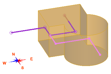
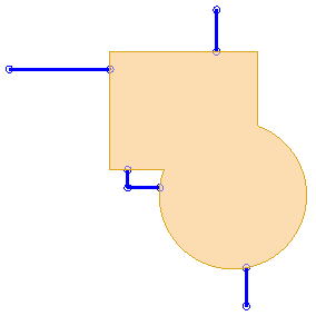
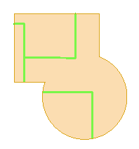
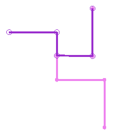
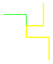
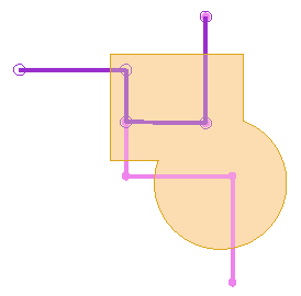
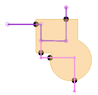
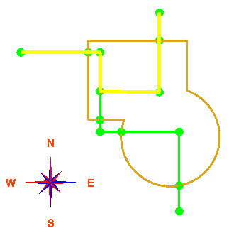
This example uses two polylines (shown in purple and pink) and a solid as the boundary (shown in light brown). These are shown as displayed in MS3D for illustrative purposes. The two polylines have portions that overlap.
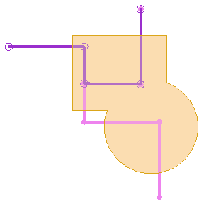
Plan View:
|
Before - original polylines and bounding solid
|
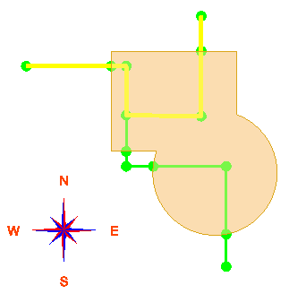
After - polylines internal and external to the boundary solid
|
-
External option: -ext
This will return the portion of the polylines (polylines.srv) that are outside of the surface (solid.shl). Polylines are split at intersection points.
sclip.exe –prm param.cod –srv polylines.srv -shl solid.shl –ext external.srv
To use a polygon as the boundary (instead of a surface), use the syntax:
sclip.exe -prm param.cod -srv polylines.srv -bnd polygon1.srv -ext externalP.srv
The results are the same as shown above.
-
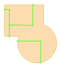
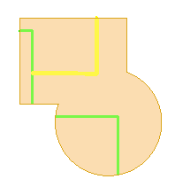
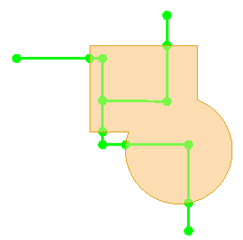
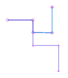
Internal option: -int
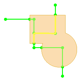
This will return the polylines inside the surface (solid.shl). This will self-intersect polylines by splitting them at intersection points. The resulting polylines that are coincident, but are not merged as shown by the query highlighting in the images below.
sclip.exe –prm param.cod –srv polylines.srv -shl solid.shl –int internal.srv
|
|
|
|
To use a polygon as the boundary (instead of a surface), use the syntax:
sclip.exe -prm param.cod -srv polylines.srv -bnd polygon1.srv -int internalP.srv
The results are the same as shown above.
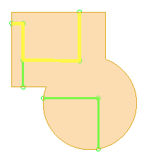
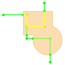
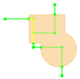
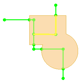
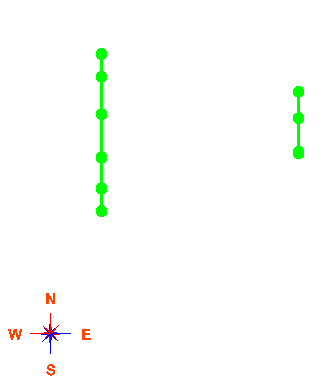
The "-opt" option will return the same results as above but, where possible, the resulting polylines will be merged and have no overlapping segments (as shown by the query highlighting in the images below - compare these to the images above).
sclip.exe –prm param.cod –srv polylines.srv -shl solid.shl –int OptInternal.srv -opt
|
|
|
|
When using the "-opt" option without a surface (solid) boundary, use the "-ext" (external) switch. The resulting polylines will be merged (if possible) and have no overlapping segments (as shown by the query highlighting in the images below - compare the two images on the right with the original, overlapping polylines shown on the left).
sclip.exe –prm param.cod –srv polylines.srv –ext Opt.srv -opt
|
|
|
|
In this case, there is nothing to do. The resulting polylines are identical to the original input polylines. Compare the images below to the image of the original polylines, just above on the left.
sclip.exe -prm param.cod -srv polylines.srv -ext i_only.srv -i
|
|
|
|
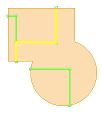
Use the "-n" option to split the polylines at the boundary surface (solid). Note you must use the "-ext" keyword in the command line syntax. When the "-int" keyword is used, it is an incorrect combination of options.
sclip.exe -prm param.cod -srv polylines.srv -shl solid.shl -ext split1.srv -n
|
|
|
The resulting polylines are not optimized, as shown by the query highlighting below:
|
|
|
To create optimized results when splitting the polylines, add the "-opt" option to the command line syntax:
sclip.exe -prm param.cod -srv polylines.srv -shl solid.shl -ext split1-opt.srv -n -opt
The resulting polylines are shown by the query highlighting below. Compare these two images to the images just above. Notice the resulting polylines were merged and there are no overlapping segments.
|
|
|
To find the intersection points between the polylines and the solid, use the "-x" option:
sclip.exe -prm param.cod -srv polylines.srv -shl solid.shl -x PolySolidIntersect.srv
In the plan view image below, the intersection points between the polylines and the solid are shown by the black nodes. A boundary polygon can be used instead of a solid.
This option works with the "-ext" option and is similar to the "-n" option described above, except that the resulting polylines are not split. The point of intersection is added to the polylines.
To add the intersection points to polylines where they intersect a polygon boundary (polygon1):
sclip.exe -prm param.cod -srv polylines.srv -bnd polygon1.srv -ext IntersectPolylines1.srv -a
To add the intersection points to polylines where they intersect a solid boundary (solid.shl):
sclip.exe -prm param.cod -srv polylines.srv -shl solid.shl -ext IntersectPolylines1Solid.srv -a
In these examples, the resulting polylines are not clipped at the boundary, but instead a node is added to the resulting strings at the intersection points (see highlighted polyline below with nodes added where it intersects the boundary). The image on the left uses a polygon boundary and the one on the right uses a solid boundary.
|
|
|
sclip.exe –prm param.cod –srv polylines.srv –ext validate.srv -v
This validates the polylines for the purpose of triangulation, and does no merging. The results are displayed in dashed light blue, and they are coincident with the original polylines.
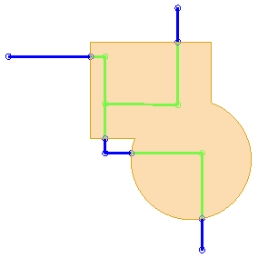
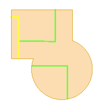
To output polylines that are co-linear to a polygon boundary, use the following syntax.
sclip.exe -prm param.cod -srv polylines3.srv -bnd polygon1.srv -par colinear.srv
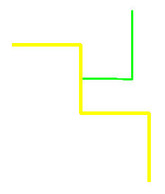
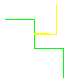
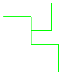
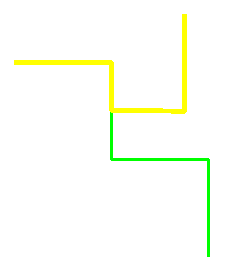
The image below on the left shows the original polyline (in blue), the bounding polygon (dashed, goldenrod color), and the resulting co-linear polylines (in green). The image on the right shows only the resulting co-linear polylines.
|
|
|

In the image on the left, notice there are 4 points on the polyline that are coincident to the boundary polygon but they are not considered as co-linear (along the curved portion of the boundary polygon). This is because these 4 nodes occur on the boundary polygon, but the line segment is not co-linear. This option can also be used with a solid (surface) boundary. If a surface (solid) is used as the boundary, beware the a single node on the polyline can be coincident as well as co-linear with the surface.
Use the "-intx" option to create polygons (closed polylines) when clipping against a polygon boundary (not a solid). The result is different from the "-int" option discussed.
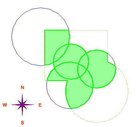
This case starts with multiple polygons (blue color) and a boundary polygon (dashed goldenrod color).

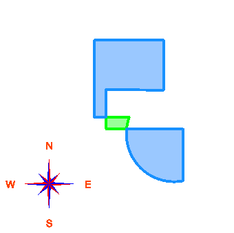
Using the "-intx" option, the result is closed polygons (shown below in green, with fill turned on).
sclip.exe -prm param.cod -srv circles2.srv -bnd polygon1.srv -intx PolyInt.srv
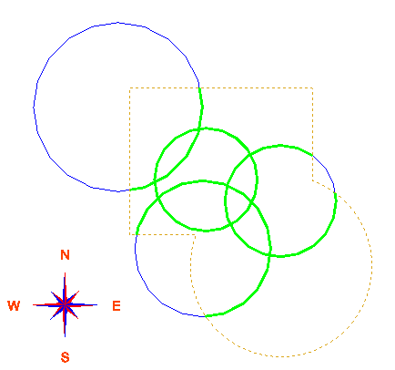
The "-intx" option is different from the "-int" option discussed above. [Note: the "-int" option above uses a boundary solid, instead of a boundary polygon]. Using the "-int" option, the polygons are clipped by the boundary polygon to create polylines, not polygons. The results are displayed in green in the image below.
sclip.exe -prm param.cod -srv circles2.srv -bnd polygon1.srv -int PolyInt1.srv
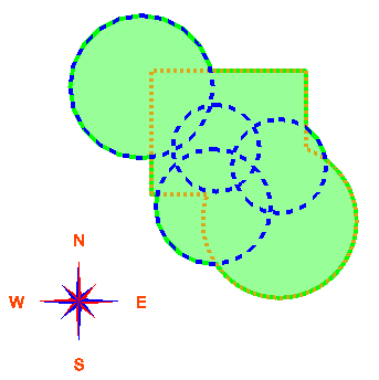
To generate the union of polygons with a boundary polygon, use the syntax:
sclip.exe -prm param.cod -srv Circles2.srv -bnd polygon1.srv -union union.srv
The image on the left below shows all of the components used (blue circle polygons, and dashed goldenrod polygon boundary), plus the results (in green). The image on the right displays the resulting polygon from the union of the circles and polygon boundary.
 |
 |
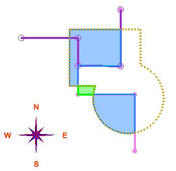
Use the following syntax to find the difference between polylines (or polygons) a boundary polygon.
-
To find the difference SRV - BND use the "diff1" option:
sclip.exe -prm param.cod -srv polylines.srv -bnd polygon1.srv -diff1 diff1.srv
-
To find the difference BND - SRV use the "diff2" option:
sclip.exe -prm param.cod -srv polylines.srv -bnd polygon1.srv -diff2 diff2.srv
The image below shows the polylines from the survey file (in pink and purple), and the boundary file (dashed, in goldenrod color). The difference between the polylines and the boundary created polygons; "diff1" (srv-bnd) is displayed in green, and "diff2" is displayed in blue. Only the "diff" results are displayed in the image on the right.
 |
 |
-
Clip a set of drillholes against a solid to output a file in coding format or output a survey file with the intersection points: -drh
Clipping a set of drillholes against a solid, or group of solids, is a more advanced use of SCLIP. There are multiple ways to code drillholes in MineSight. This is just one of many methods that can be used.
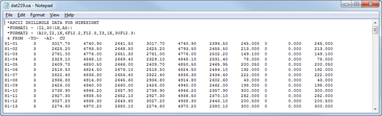
Input into SCLIP consists of an ASCII file of drillhole data in M219V1 format, a solid in .shl format, and an attribute file which defines the code value(s) as per the shell file(s). In the example shown here, there is only 1 shell file (a solid).
First create the input files for SCLIP
If you are using MineSight drillhole and survey files (Files 11 & 12), you can use MSBasis program M219V1 via procedure P21901.DAT to create the ASCII file in the proper format for use in SCLIP. NOTE: This is not a recommended method of coding intervals if you are using MSTorque drillhole data as you would need to perform several preliminary steps.
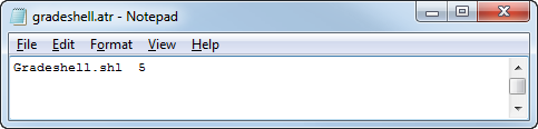
Clipping makes use of an "attribute" file. This attribute file specifies the filename of the solid shell file(s) and the code value(s) to apply to those intervals that occur within the solid(s). In the example attribute file "gradeshell.atr" shown below, there is only 1 solid (Gradeshell.shl) and its corresponding code is 5.
Example ATTR file:
Create the output file in the format for input into MSBasis program, M205V1 for coding drillhole intervals.
sclip.exe -drh dat219.oa -attr Gradeshell.atr -drill dat205.s2
"-drh" designates the drillhole ASCII file (in M219V1 format)
"-attr" designates the attribute file
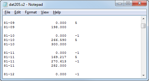
"-drill" designates the output file; output is in M205V1 format. The output file, "dat205.s2" will be used as input by M205V1 via p20501.dat to code the drillhole intervals with the proper code. A portion of this output file is shown below; drillhole number is in the first column on the left, then the intervals and code value. For example, in drillhole "81-10", the code is "-1" (=unset) from 0 to 266.58, then from 266.59 to 300, the code is 5.
To use this output file as input to MSBasis program M205V1 in order to load the codes in to the drillhole intervals, please refer to the documentation for M205V1 in M200.PDF [the MSBasis PDF documentation is installed into your %medexe%\helpdoc directory].
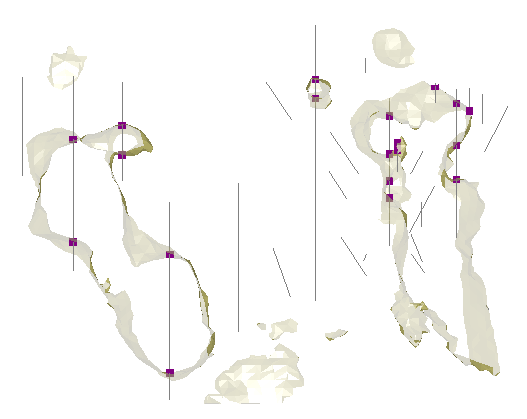
sclip.exe -drh dat219.oa -attr Gradeshell.atr -x GSInt2.srv
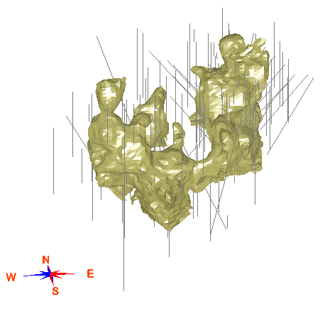
This option utilizes the "-x" option to obtain the intersection points. The two images that follow illustrate the results in MS3D; the intersection points are displayed as purple squares and those points occur wherever a drillhole spears the solid (either going into, or out of the solid).
3D view, displaying the drillhole traces, the solid and the intersection points:

Cross sectional, volume clipped, oblique view displaying the drillhole traces, the solid and the intersection points: